Volt Eton Solenoid Wiring Diagram
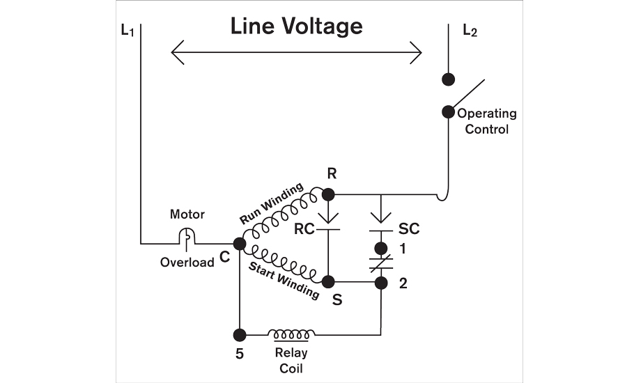
Volt Eton Solenoid Wiring Diagram. So let's run a wire from the solenoid negative to the middle pin (collector) of the transistor. The diagram below shows the wiring for a single phase motor and the path through the contactor and overload NOTE : These notes and diagrams provide a schematic method of achieving the control but it remains the responsibility of the installer to ensure that any.

There are some variations like whether or not to draw a circle around a transistor or how many lightning bolt lines to use with photon emitters and detectors, but that's about it.
The diagram below shows the wiring for a single phase motor and the path through the contactor and overload NOTE : These notes and diagrams provide a schematic method of achieving the control but it remains the responsibility of the installer to ensure that any.
Following table shows wire colors related to electrical circuits. It is, like relays and motors, an inductive load (aka an IC buster, go read on back EMF if it is not already done!). Solenoids to make the transfer of the main contacts from. source to source.


0 Response to "Volt Eton Solenoid Wiring Diagram"
Post a Comment