Volt Electric Motor Wiring Diagram
Volt Electric Motor Wiring Diagram. This is how I built an electric motorcycle. When an electric starter kit is installed, the voltage regulator and its ground wire are replaced by a voltage rectifier/regulator unit permitting a com-pletely isolated AC circuit.

When an electric starter kit is installed, the voltage regulator and its ground wire are replaced by a voltage rectifier/regulator unit permitting a com-pletely isolated AC circuit.
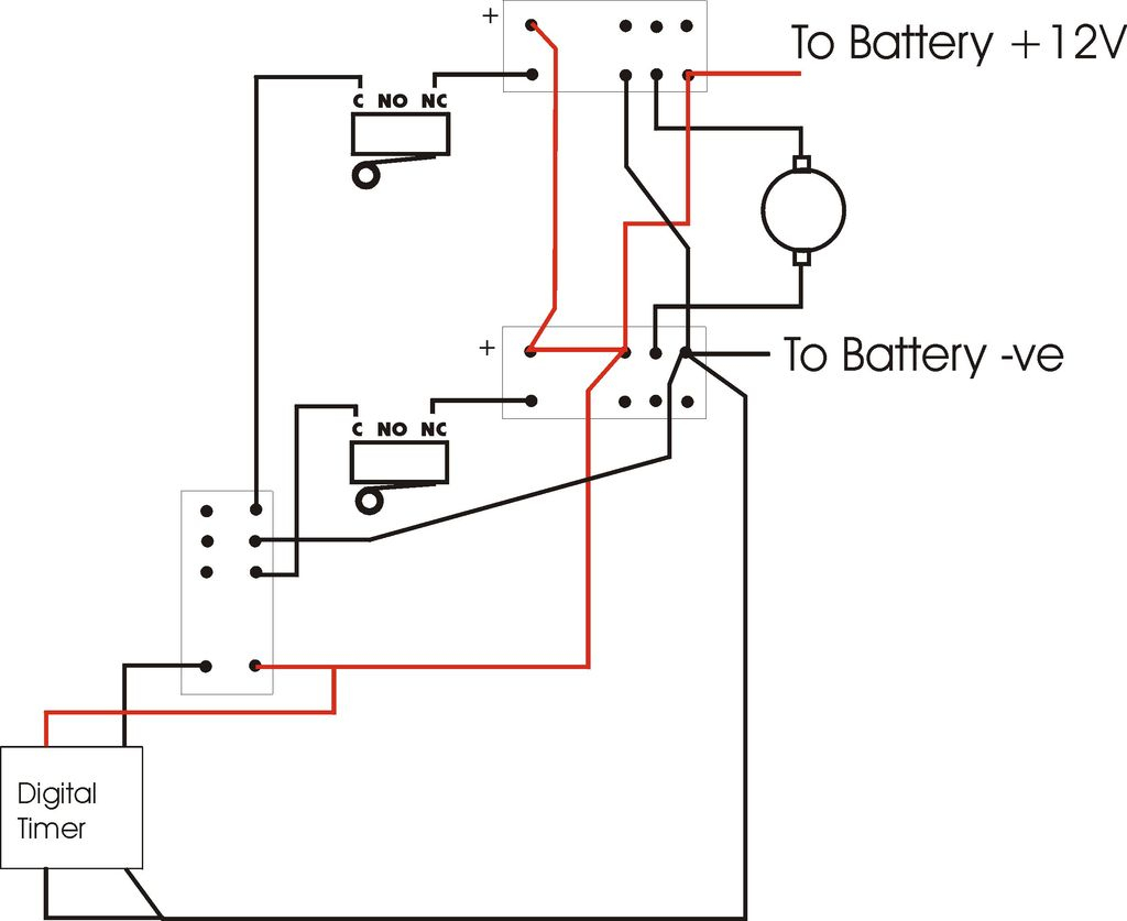
A DC motor has two input terminals, one positive and one negative.
12 Volt Relay Wiring Diagram | Wiring Diagram

Ac Motor Speed Picture: Century Ac Motor Wiring

[DIAGRAM] 120 Volt Motor Switch Wiring Diagram FULL ...
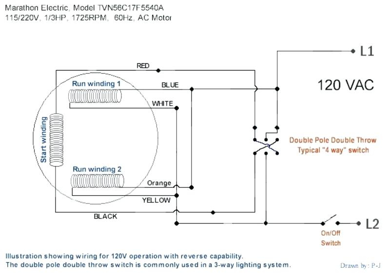
115 Volt Ac Single Phase Motor Armature And Fields Wiring ...

220v Single Phase Motor Wiring Diagram - Hanenhuusholli

Wiring advice for a reversing dc motor (like an anchor winch.)

[DIAGRAM] High Voltage Motor Wiring Diagram FULL Version ...

Electrical Control Circuit Schematic Diagram of Capacitor ...

110 220 Volt Electric Motor Wiring | schematic and wiring ...
WIRING DIAGRAM A wiring diagram shows, as closely as possible, the actual location of all component When a motor must be started and stopped from more than one location, any number of Start and Wiring Diagram. MC Motor Starter Wiring Diagram With CB, MC, O/L, NO, NC. This is how I built an electric motorcycle.

0 Response to "Volt Electric Motor Wiring Diagram"
Post a Comment