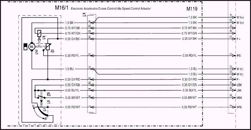
01 Frontier Throttle Body Diagram Wiring Schematic
01 Frontier Throttle Body Diagram Wiring Schematic. Circuit Descriptions of the GM Electronic Throttle Body. Also I show you how you can figure out what each wire on your sensor.

To locate the correct wiring diagram for your vehicle you will need: Make and Model of ABS ECU.
How is a Wiring Diagram Different from a Schematic?
1993-1995 R129 SL Engine Wiring Harness Problems - Page 10 ...

Ls3 Throttle Wiring Diagram - Wiring Diagram
Wanna bring my 3rd gen back to life, looking for a EFI ...

Nissan Xterra 4 0 Engine Diagram - Wiring Diagram
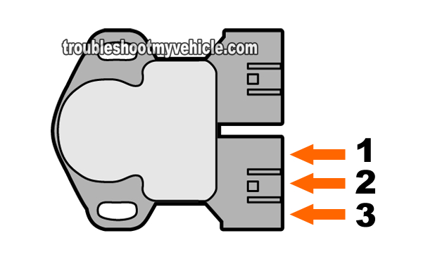
Part 1 -How to Test the Throttle Position Sensor (Nissan 3.3L)

4 3 Chevy Tbi Sensor Wiring Diagram - Wiring Diagram Networks

Need Help! on idle cable! - Harley Davidson Forums

AIR INTAKE SYSTEM

| Repair Guides | Transmission/transaxle (2003 ...
Here is a quick video on how to test a Throttle Position Sensor TPS with a multimeter. For additional Wiring Diagrams info, see Electrical System (E) in the Technical Bulletins Index. General Electric Voltage Regulator Wiring Diagram

0 Response to "01 Frontier Throttle Body Diagram Wiring Schematic"
Post a Comment