Volt Potentiometer Wiring Diagram
Volt Potentiometer Wiring Diagram. There are just two things that will be found in almost any Potentiometer Wiring Diagram. A potentiometer is a handy little component often used to control the volume of music equipment, brightness of a light, and more.

Wiring a potentiometer as a rheostat.
Use all three terminals to create a voltage divider to control or adjust voltage.

Linear Potentiometer Wiring Diagram - Wiring Diagram

Electronics Tutorial Experiments DC Circuits Potentiometer ...
.png)
Describe briefly, giving the necessary circuit diagram ...
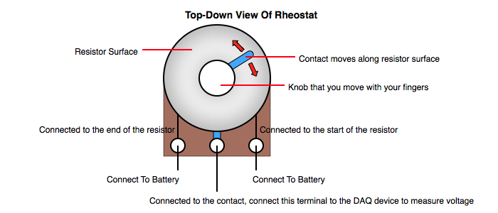
Rheostat
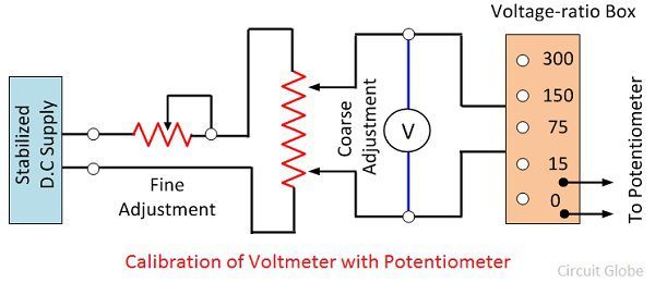
Calibration of Voltmeter, Ammeter & Wattmeter using ...

BLDC Motor control using Arduino | Speed control with ...
Rheostat, Variable Transformer (VT1)

Potentiometer voltage divider [62978] - Circuit and Wiring ...
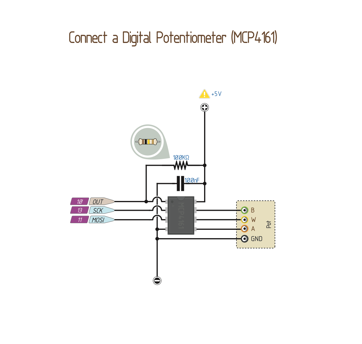
Wiring a Digital Potentiometer with MCP4161 | 14core.com
A potentiometer, or "pot" is a variable resistor with three terminals and a shaft that can be turned in either direction. WIRING DIAGRAM A wiring diagram shows, as closely as possible, the actual location of all component parts of the device. F ELECTRICAL WIRING DIAGRAM (System Circuits).

0 Response to "Volt Potentiometer Wiring Diagram"
Post a Comment