Volt Hydraulic Solenoid Wiring Diagram
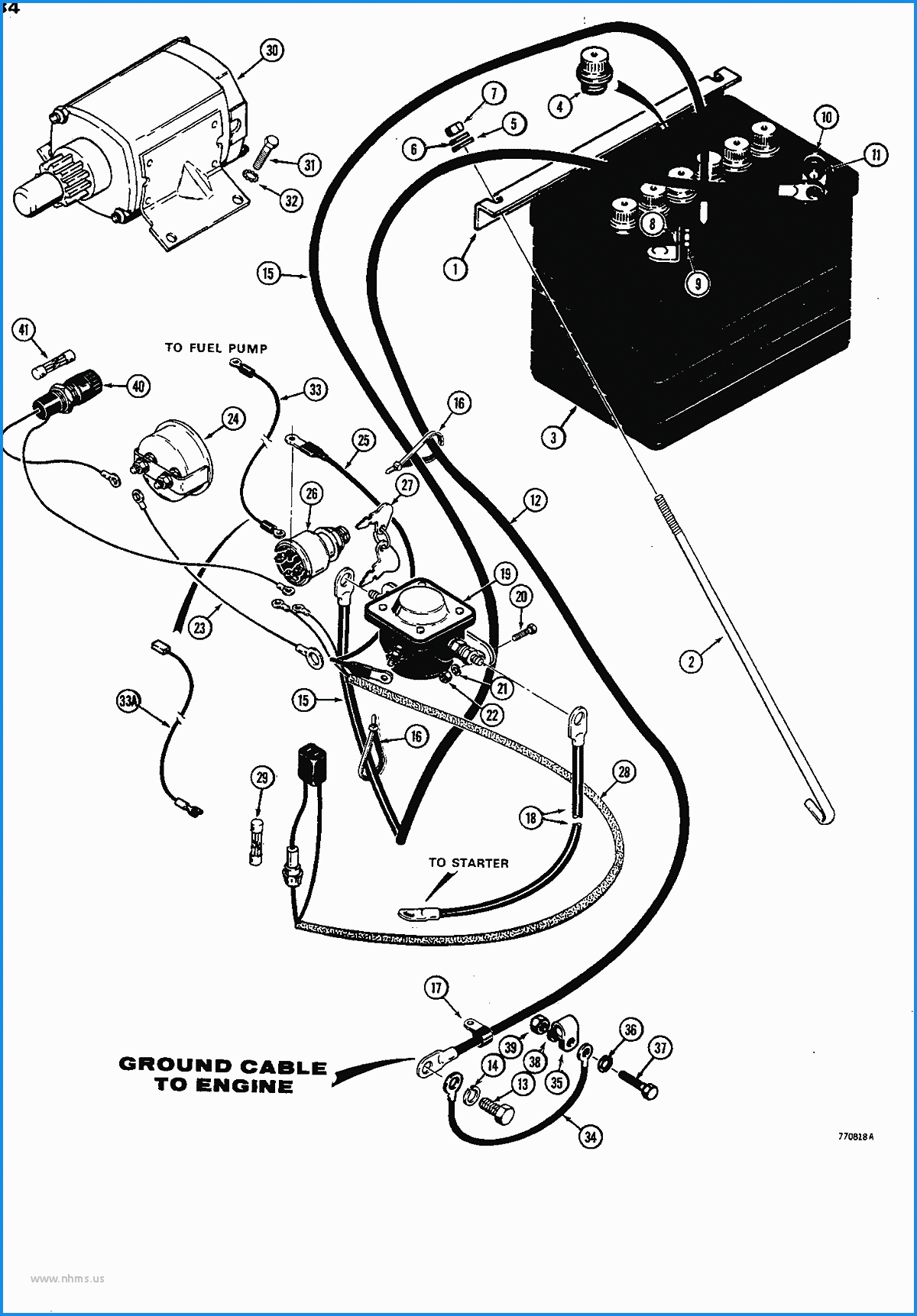
Volt Hydraulic Solenoid Wiring Diagram. Wiring diagrams help technicians to see how the controls are wired to the system. WIRING HARNESS CONFIGURATION DIAGRAMS - Overall Wiring Diagram.

Legend of wiring diagram of manual transmission.
If the circuit diagram designation is boxed in with broken lines this means that the circuit diagram is not standard on all market or vehicle models.

How to Electrically Wire Up a 12 Volt DC Hydraulic Power ...

Concentric 12 Volt DC Power Unit, Solenoid Operation ...

HydraForce 6302012 Solenoid Valve Coil, Wire Leads, 12v DC ...

Hydraulic Solenoid Valve Wiring Diagram - Wiring Diagram ...
Air Compressor 12 Volt Solenoid Wiring Diagram - Wiring ...

Monarch Hydraulic Pump Wiring Diagram

HYDRA FORCE 12 VDC N.C. SOLENOID VALVE | Solenoid Valves ...

12v Hydraulic Power Pack Wiring Diagram Sample
[DIAGRAM] Water Pump Diagrams Wiring Diagram FULL Version ...
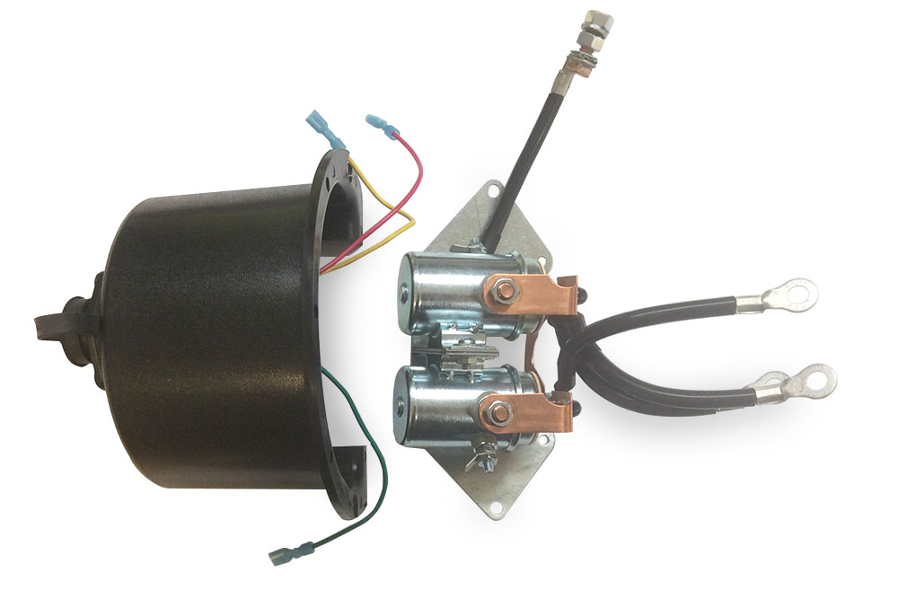
When contacting the two leads in reverse, there should be no continuity. (c) Use a volt/ohmmeter with high SOLENOID An electromagnetic coil which forms a magnetic field when current flows, to move a plunger, etc. The diagram provides visual representation of an electrical arrangement. Provides circuit diagrams showing the circuit connections.

0 Response to "Volt Hydraulic Solenoid Wiring Diagram"
Post a Comment